- Home
- Service Features
- Technical Basics
Term explanations
Grating period (interval T)
A grating is a continuous series of lines and spaces printed on the scale.The width of one line is called the period (sometimes referred to as the interval) of the grating. The lines and spaces are accurately placed on the scale.
Signal period
When scanning the grating, the encoder head produces sinusoidal signals with a period equal to the grating period.
Interpolation
The sinusoidal signal period can be electronically divided into equal parts. The interpolation circuitry generates a square-wave edge for each division.
Measuring step (resolution)
The smallest digital counting step produced by an encoder.
Line rates
Number of the grating periods per rotation. (Modular Angle Encoders).
Reference pulse (reference mark)
There is an additional track of marks printed next to the grating to allow a user to find an absolute position along the length of the scale. A one increment wide signal is generated when the encoder head passes the reference mark on the scale. This is called a “true” reference mark since it is repeatable in both directions. Subsequent electronics use this pulse to assign a preset value to the absolute reference mark position.
Fault detection signal
The fault detection signal indicates fault conditions such as an interruption in the supply lines, failure of the light source, etc.
For example, it can be used in the automated production for the machine switch-off.
Accuracy
This is a fundamental characteristic, which is specified with an accuracy grade (e.g. ±5 µm/m).
Online signal stabilization
During moving the amplitude, offset-error, amplitude differences and phase shift error are measured and stabilized cyclic.
Abbe error
Measuring error due to lateral distance between the measuring system and the machining level.
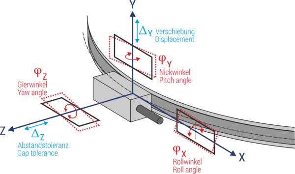
Yaw angle, pitch angle, roll angle, displacement, gap tolerance
Mounting tolerances of the scanning head relative to the scale.

